Tool Flow
Overview
Collapsed
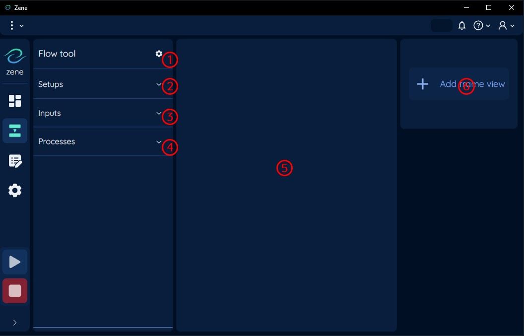
1: Flow Tool Setting Button
Click to open the flow tool setting area.
2: Setup Tool Button
Click to open the setup tool flow area.
3: Input Tool Button
Click to open the input tool flow area.
4: Process Tool Button
Click to open the process tool flow area.
5: Tool Setting Area
When a tool is selected, this is the area where the tool setting is displayed.
See Tool Setting Area for more information.
6: Frame View Area
This is the area where the frames are displayed.
See Frame View for more information.
Expanded
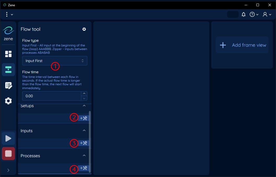
1: Flow Tool Setting Area
This is the area where the flow setting is displayed.
2: Add Setup Tool Button
Click to open the setup tool selector, see Tool Selector for more information.
3: Add Input Tool Button
Click to open the input tool selector, see Tool Selector for more information.
4: Add Process Tool Button
Click to open the process tool selector, see Tool Selector for more information.
Tool Selector
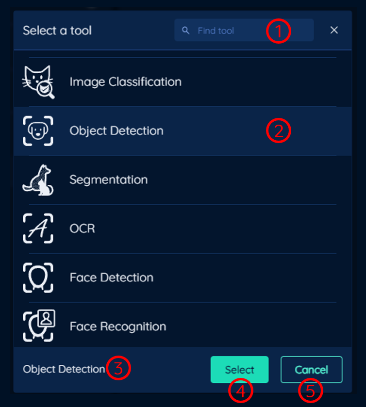
1: Find Tool Search Box
Type to search for a tool. The tool selector will filter the tools based on the search term.
2: Tool Highlight
The tool highlight indicates the tool that is currently selected.
3: Tool Name Indicator
Display the currently selected tool name.
4: Select Button
Click to Select the currently highlighted tool to add to the flow.
5: Cancel Button
Click to Cancel the tool selection.
Tool selector is a modal that allows the user to select a tool to add to the flow. The image above shows an example of the tool selector for process flow, where we have clicked on Object Detection tool. (The tool selector for setup and input flow is similar just populated with different tools.)
Flow Area
Drag and Drop Zones (Flow Areas)
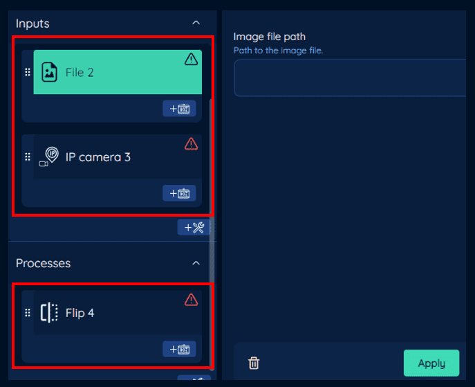
In the image above the main flow areas are highlighted in red. There are three (3) main flow areas:
SetupInputProcess
See Expanded section for a visual representation of the flow areas.
A flow area is where the user can drag and drop tools to create a flow. The user can reorder the tools in the flow area by dragging and dropping the tool to the desired position.
The order of the tools in the flow area is important as it determines the order of execution of the tools.
A tool from can only be dropped in the flow area of the same type. For example, a Setup tool can only be dropped in the Setup flow area.
Tool Object Anatomy
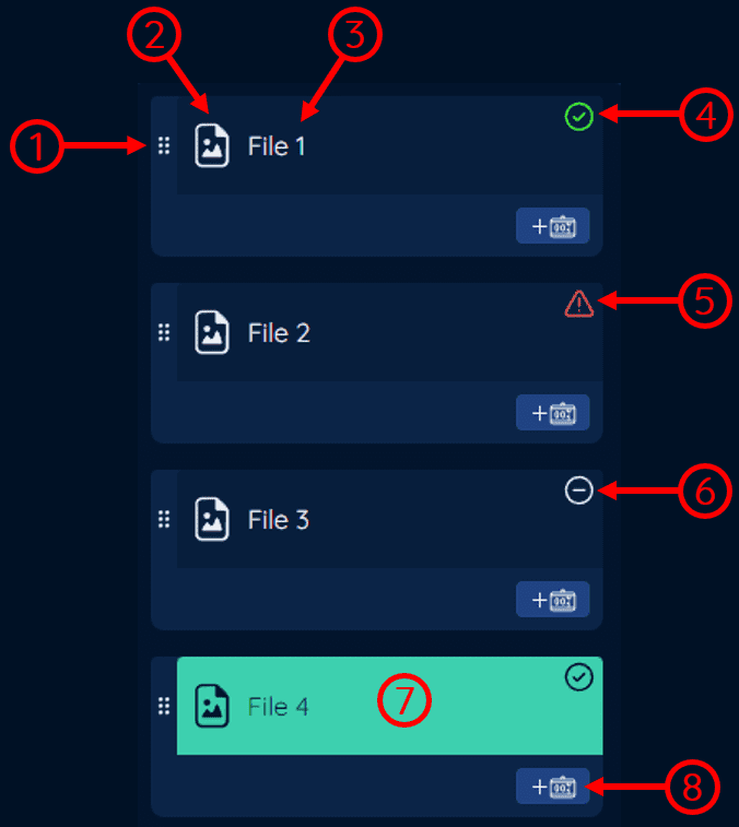
1: Drag Handle
This indicates that the tool can be dragged and dropped. The user can click and drag to move the tool around the flow area.
2: Tool Icon
This is the icon of the tool, each tool has a unique icon.
3: Tool Name
This is the name of the tool, for this example the tool name is File 1. The user can change the name of the tool in the tool setting area. See Tool Setting Area for more information.
4: Tool Readiness Indicator (Ready)
This indicates that the tool is ready to be run.
5: Tool Readiness Indicator (Not Ready)
This indicates that the tool is not ready to be run. Select the tool to see the reason why the tool is not ready in the tool setting area.
6: Tool Readiness Indicator (Disabled)
This indicates that the tool is disabled. If a tool is disabled, it will not be run when the flow is executed. The user can change this setting in the tool setting area.
See Tool Setting Area for more information.
7: Selected Tool
This indicates that the tool is selected. The user can select a tool by clicking on it. Once the user have selected a tool, the tool setting area will be populated with the tool setting for the selected tool.
For this example File 1, File 2, File 3 are not selected, while File 4 is selected.
8: Add Nested Tool Button
Click to add a nested tool to the tool. The nested tools vary depending on the tool type.
See Tool Types for more information.
Tool Types
General Tools

There are two types of general tools, tools with and without counter. The tools with counter are indicated having a button on the bottom-left of the tool object, indicated in the image with number 3.
1: Tool with Counter
This is a tool with counter. A counter is a number that indicates the number of times the tool result conditions are met.
The tool with counter object surrounds the counters, indicated in the image with number 2.
2: Counter Tool Area
This is the area where the counter tool is located.
Counter tool cannot be drag and drop as all the counter tools of that tool are executed after the tool is executed.
3: Add Counter Tool Button
Click to add a counter tool to add the counter tool.
4: Tool without Counter
This is an example of a tool without counter. Note that the tool object does not have a button on the bottom-left of the tool object.
Counter Tool
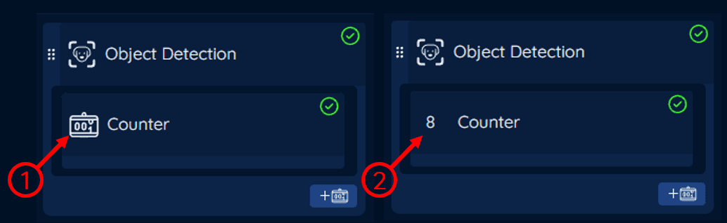
Counter tool is a tool that has a counter. The counter is a number that indicates the number of times the tool result criteria is met.
1: Icon - Not Running
Counter icon when the tool is not running.
2: Icon - Running
Counter icon changes from icon to the count number when the tool is running. In this example the count is 8.
If-Then Tool
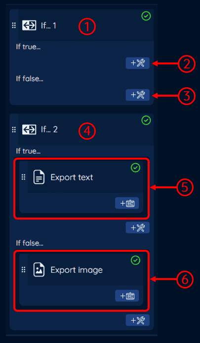
If tools are tools that have two (2) branches, If true... and If false.... The If true... branch is executed if the tool result conditions are met, while the If false... branch is executed if the tool result condition are not met.
See If-Then - Conditions for more information on the tool result conditions.
If... tool has only one level of nested tools, the user cannot add another If... tool in either of the If... tool branches.
1: If Tool (no nested tools)
This is an example of an If tool with no nested tools.
2: Add Nested Tool Button - True Branch
Click to add a nested tool to the If true... branch of the If tool.
3: Add Nested Tool Button - False Branch
Click to add a nested tool to the If false... branch of the If tool.
4: If Tool (with nested tools)
This is an example of an If tool with nested tools. In the If true... branch, there is a Export text tool, while in the If false... branch, there is a Export image tool.
5: Nested Tool Area - True Branch
This is the area where the nested tool for the If true... branch is located. Similar to the main flow area, the user can drag and drop tools in this area and the order of the tools in this area is important as it determines the order of execution of the tools.
6: Nested Tool Area - False Branch
This is the area where the nested tool for the If false... branch is located. Similar to the main flow area, the user can drag and drop tools in this area and the order of the tools in this area is important as it determines the order of execution of the tools.
The user cannot drag and drop a tool from the If true... branch to the If false... branch and vice versa.
Pop-up Alert Tool

1: Popup Tool
This is an example of a popup tool with a nested tool (LINE Notify). When the popup tool is executed it will display a popup message on all client UIs and run the nested tools.
2: Popup Tool Area
This is the area where the nested tool for the popup tool is located. Similar to the main flow area, the user can drag and drop tools in this area and the order of the tools in this area is important as it determines the order of execution of the tools.
The user cannot drag and drop a tool from the popup tool area to the main flow area and vice versa.
2: Add Nested Tool Button
Click to add a nested tool to the popup tool.
Tool Setting Area
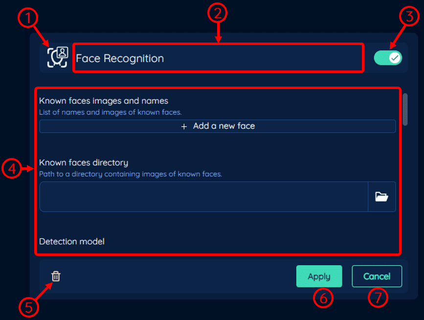
1: Tool Icon
This is the icon of the selected tool.
2: Tool Name
This is the name of the selected tool, the user can change the name of the tool by clicking on the name.
3: Enable/ Disable Toggle
This is the toggle to enable or disable the tool. When the tool is disabled, it will not be executed when the flow is running.
4: Tool Setting Area
The tool setting area is where the user can configure the tool settings for the selected tool. The image above shows the tool setting area for the Face Recognition tool.
5: Delete Tool Button
Click to delete the selected tool.

Popup confirmation when deleting a tool. Click Delete to delete the tool.
6: Apply Button
Click to apply the changes made to the tool settings.
The user must click the apply button to apply the changes made to the tool settings.
7: Cancel Button
Click to cancel the changes made to the tool settings.